Interfaces
I am using two types of interfaces, Velleman K8055's & Mirrorbow's.
Both types of interfaces are USB controlled. Here are the details:-
Velleman K8055 Interfaces
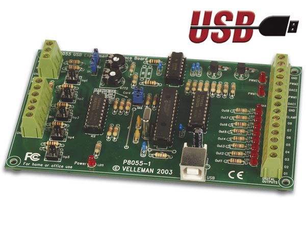
Specifications
5 digital inputs (0= ground, 1= open) (on board test buttons provided)
2 analogue inputs with attenuation and amplification option (internal test +5V provided)
8 digital open collector output switches (max. 50V/100mA) (on board LED indication)
2 analogue outputs:-
- 0 to 5V, output resistance 1K5
- PWM 0 to 100% open collector outputs max 100mA / 40V (on board LED indication)
general conversion time: 20ms per command
power supply through USB: approx. 70mA
dimensions: 145 x 88 x 20mm / 5.7 x 3 x 0.8"
Download Illustrated Assembly Guide
Download Programming Userguide
Mirrorbow Interfaces
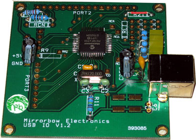 Specifications
General
26 IOs – 24 general IOs + PWM output and Frequency measure input
Power – USB Powered
Maximum loading on any output 10mA subject to not exceeding 100mA total on all output pins
All IOs logic level except for inputs configured as Analogue to Digital which have a range of 0
to 5V
Maximum read speed (from host PC) approx 1mS (Windows on the host usually defaults to
500uS for a command write and 500uS for a response, thus a tight software loop on the host can switch the state of a port every 1mS)
PWM
Output frequency range from 2.9KHz to 1MHz with programmable mark/space
Frequency Counter
Input frequency range 0.2Hz to 5.25MHz logic level
Port1 change poll mode
Any change returns a message (including changes to output state on the port)
Polled every 25mS
Port2 change interrupt mode
Any change on lower 4 bits of port2, restricted to changes on pins defined as inputs
Will catch fast changes, however each change interrupts the processor on the USB 25IO so subjecting this input to continued rapid changes can result in loss of communication with the
board...care must be taken with this mode
Recommended max change rate – 40 times/sec
Use this mode if you have short duration pulses which could be missed in poll mode above
Analogue to Digital Converter mode
Selectable as :-
Specifications
General
26 IOs – 24 general IOs + PWM output and Frequency measure input
Power – USB Powered
Maximum loading on any output 10mA subject to not exceeding 100mA total on all output pins
All IOs logic level except for inputs configured as Analogue to Digital which have a range of 0
to 5V
Maximum read speed (from host PC) approx 1mS (Windows on the host usually defaults to
500uS for a command write and 500uS for a response, thus a tight software loop on the host can switch the state of a port every 1mS)
PWM
Output frequency range from 2.9KHz to 1MHz with programmable mark/space
Frequency Counter
Input frequency range 0.2Hz to 5.25MHz logic level
Port1 change poll mode
Any change returns a message (including changes to output state on the port)
Polled every 25mS
Port2 change interrupt mode
Any change on lower 4 bits of port2, restricted to changes on pins defined as inputs
Will catch fast changes, however each change interrupts the processor on the USB 25IO so subjecting this input to continued rapid changes can result in loss of communication with the
board...care must be taken with this mode
Recommended max change rate – 40 times/sec
Use this mode if you have short duration pulses which could be missed in poll mode above
Analogue to Digital Converter mode
Selectable as :-
- No ADC inputs (all logic IOs) o 2 ADC inputs
- 12 ADC inputs
Measurement in the range of 0V to 5V
Resolution 10 bit , returning in hex 0000 to 03FF
Servo Mode
Port2 can be configured as up to 8 servo outputs
Designed to drive the signal line of standard servos
Each output can be either off or programmed to output a pulse of width between less than
1mS to greater than 2mS. Each servo output will continue to transmit the programmed pulse chain continually.
Data Acquisition
Master sample frequencies of 16kHz, 8kHz, 4kHz, 2kHz, 1kHz and 500Hz
Port1 and Port2 digital acquisition up to 16Khz
Analogue to Digital acquisition up to 16Khz
Analogue to digital data channel modes of 1 channel, 2 channels, 12 channels with Port1 and
Port2 state
Download PDF Userguide
